Understanding the intricate diagrams and connections can be daunting when loading cell wiring. However, with the proper knowledge and guidance, you can master the art of wiring load cells effectively. In this comprehensive analysis, we will delve into the basics of load cell wiring, decode eTAZ systems load cell wiring diagrams, provide a step-by-step guide for wiring your load cell, troubleshoot common wiring issues, ensure accuracy and longevity in load cell wiring, offer advanced tips for expert wiring, and conclude with further resources for your reference.
Introduction to Load Cell Wiring Basics

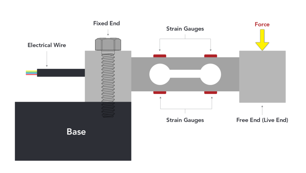
The crucial aspect of wiring is at the core of any load cell system. The fundamental role of a load cell, as a device that translates physical force into a measurable electrical output, hinges significantly on its wiring integrity. Wiring is the conduit through which data is transferred from the load cell to the display or processing unit, making understanding its basics beneficial and necessary. Load cells, diverse in their applications, require meticulous attention to their wiring configurations to ensure the accuracy of the measurements they provide. This includes a keen awareness of the color codes used in wires, which denote their function, the importance of correct polarity to avoid measurement errors, and the necessity for secure connections that mitigate the risk of signal disruption.
Decoding the eTAZ Load Cell Wiring Diagram
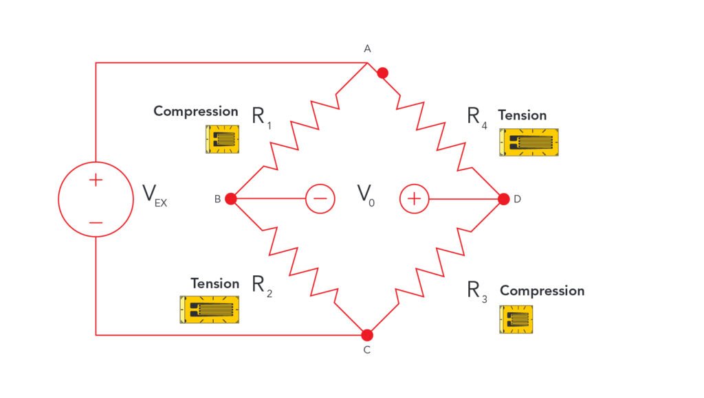
Navigating through the eTAZ load cell wiring diagram requires a focused understanding of its components and their roles within the system. The diagram serves as a map, illustrating how the signal, excitation, and sense wires are interconnected to ensure the load cell functions correctly. It’s crucial to identify each wire’s purpose:
- The excitation wires power the load cell.
- The signal wires transmit the measurement data.
- The sense wires compensate for changes in signal due to cable resistance.
By carefully following the diagram provided by eTAZ, users can make precise connections that align with the load cell’s design. This step is fundamental in harnessing the full potential of the eTAZ load cell, as it lays the groundwork for accurate force measurement and data integrity. Emphasizing the importance of this understanding can lead to the successful setup and operation of the load cell, thereby optimizing its performance and reliability in various applications.
Step-by-Step Guide to Wiring Your Load Cell

Wiring your load cell correctly is critical for ensuring accurate measurements. Identify each wire by its color code, corresponding to its specific function within the load cell system. Securely connect the excitation wires to the power supply terminals, ensuring they match the load cell’s requirements for voltage. Next, attach the signal wires to the input channels of your measuring or processing unit. If your load cell is equipped with sense wires, these should be connected to the same terminals as the excitation wires to allow for proper signal compensation. Maintaining the correct polarity across all connections is crucial to prevent data errors. After connecting, verify each connection’s integrity, checking for any loose ends or potential shorts. Apply appropriate insulation to each connection to safeguard against environmental factors and electrical interference.
Troubleshooting Common Wiring Issues
When facing challenges with load cell wiring, common culprits often include loose connections, inverted polarity, or compromised cables. Addressing these issues efficiently can significantly impact the functionality and reliability of your load cell system. Begin by visually inspecting the wiring for any apparent damage or wear. This might involve looking for frayed wires, signs of corrosion, or exposed conductors that could lead to shorts. Continuity tests with a multimeter can help verify the integrity of each connection and pinpoint where a break might have occurred. Ensuring that each connection is tight and secure is paramount; even a slightly loose connection can result in significant measurement discrepancies. If polarity is the issue, revisiting the wiring diagram to confirm the correct orientation of connections is a crucial step.
Ensuring Accuracy and Longevity in Load Cell Wiring

Adopting meticulous wiring practices is essential to ensure that your load cell system maintains its precision and durability over time. Emphasizing high-quality materials and connections significantly prevents premature wear and potential inaccuracies in data transmission. Regular maintenance checks are crucial; these should include verifying the integrity of the insulation, ensuring all terminals are free from corrosion, and confirming the absence of stress or strain on the cables, which could lead to fractures. It’s also advisable to periodically recalibrate your system to counter any drift in measurements and inspect for environmental impacts that might affect the wiring, such as moisture or excessive heat. By implementing these strategies, you not only safeguard your load cell’s operational lifespan but also guarantee its output’s continuous accuracy, ensuring your system remains reliable for its intended application.
Advanced Tips for Expert Load Cell
For professionals aiming to refine their load cell expertise, delving into more sophisticated strategies can substantially enhance the system’s performance and reliability. Utilizing shielded cables is a pivotal move for minimizing electromagnetic and radio frequency interference, which are familiar sources of measurement anomalies. This practice is especially crucial in environments where electrical noise is prevalent. Adopting strain relief methods is another critical consideration; these techniques prevent undue stress on wires and connections, reducing the risk of breaks and maintaining signal integrity under various conditions. Moreover, investing in premium connectors with robust and corrosion-resistant contacts can significantly impact the system’s durability and ensure consistent, accurate data transmission. Exploring differential signaling can also be beneficial, as it improves the signal-to-noise ratio by canceling out noise picked up along the cable run.
Conclusion and Further Resources
Diving into the world of load cell wiring can initially appear overwhelming, yet with the right tools and a strategic approach; it becomes an achievable task that enhances the accuracy and reliability of your measurements. The journey from grasping the basics to applying advanced wiring techniques requires continual learning and application. For those who wish to deepen their understanding or encounter unique challenges, a wealth of resources awaits. Manufacturers’ documentation often provides a first line of defense against common wiring pitfalls, offering tailored advice and specifications. Online forums and tutorials can also serve as a rich source of collective wisdom, where professionals share insights and solutions based on real-world experiences.
Additionally, workshops and courses dedicated to load cell technology and its applications offer hands-on learning opportunities for those seeking to elevate their skill set. Engaging with professional networks or industry groups can further broaden your perspective, connecting you with experts who have navigated complex wiring scenarios and can offer advice or mentorship. While this guide has laid the groundwork, the path to mastery in load cell wiring is continuous, propelled by curiosity, practice, and the pursuit of precision in your projects.
